
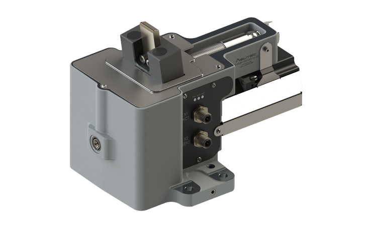
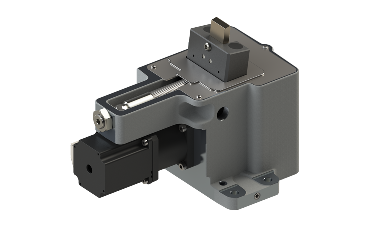
Stop module with damping ASMELBF-1000
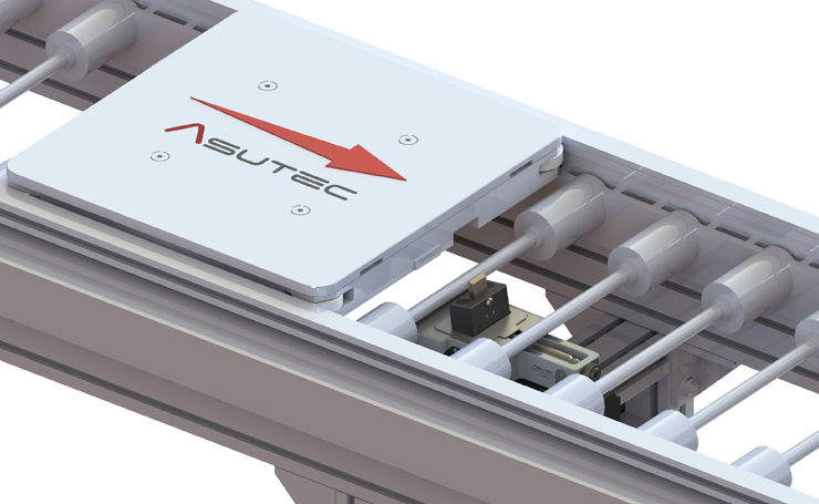
For stopping and separating of one or more accumulated workpiece carriers on a defined workpiece carrier stop surface.
The movement of the stop when stopping a workpiece carrier is detected by an integrated sensor. The integrated BlueFlow mechanism supports the damping movement until the damping end position is reached. This ensures that the damping end position is reached safely – even with lightweight workpiece carriers and low propulsion force.
Technical data
 EXECUTION AND WEIGHT
Device design: Basic housing made of aluminum and stop plate made of hardened steel.
Weights of the device ASMELBF-1000-DW-18-G5: 5,5 kg
CYCLE TIMES
Time to lower down: 1 s
Time to move up: 0,6 s
Time to retract the stop plate: 1,6 s
Minimum cycle time: 5 s
FUNCTION
The electrical stop modules ASMELBF are stop modules with integrated hydraulic damping unit.
DW (double-acting): The retraction and lowering of the stop module is done by electric energy.
In de-energized state, the stop module remains in the last reached position.
The damping is done by a self-adjusting hydraulic damping unit.
If a workpiece carrier moves to the stop, is damped and push the stop plate all the way in, then the stop plate remains in the retracted (damped) position by the integrated “BlueFlow”-mechanism. There is no counterforce on the stop, which would cause the stop plate extends when, for example, the workpiece carrier is lifted at a processing station and no workpiece carrier is pushing against the stop plate.
The extension of the stop takes place in the lower lowering position of the stop module by the restoring force of the hydraulic damping unit.
By using a hydraulic damping unit, both light and heavy workpiece carriers can be dampened and stopped.
Information on controlling the movements can be found in the operating instructions.
ELECTRICAL CONNECTION
The stop module is connected to the actuator connection and to the sensor connection. Both connections must be used. The two connection plugs have a size of M12x1 and are 5-pin.
Information on pin assignment, power supply and current consumption can be found in the operating instructions.
SPRING FORCES
Spring forces for lifting up the stop (mass of the stop not taken into account):
F1 = 26 N and F2 = 38 N.
Forces of the compression spring installed in the damping unit: 16 N – 26 N
TEMPERATURE RANGE
Temperature range: + 5°C up to + 60°C (without accessories)
MAINTENANCE WORK
No maintenance work is required.
The area around the stop must be clean and free of dirt and chips to ensure precise positioning of the workpiece carrier.
Too many different variations? - Find the suitable product!
Variants
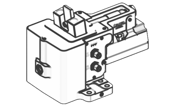
ASMELBF-1000-DW-18-G5
wide workpiece carrier weight range from 15 kg up to 1000 kg
Double-acting function, 18 mm lowering stroke
Query option for the stop plate in damping end position with inductive sensor
Connection G5: 5-pin connector M12x1 for actuators and sensors