
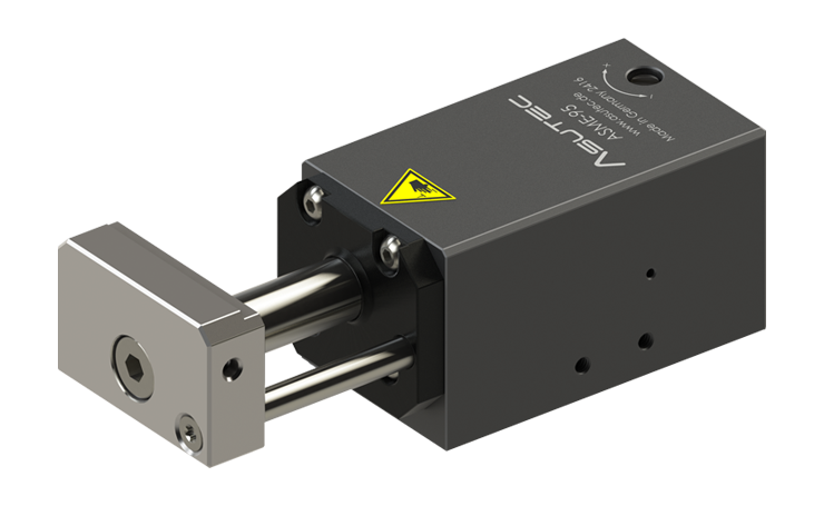
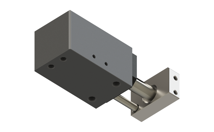
Corner stop module ASME-95
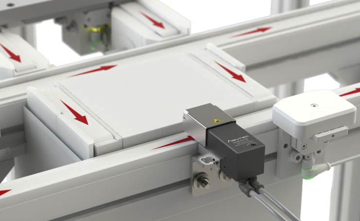
ASME-95 corner stop modules dampen and stop individual workpiece carriers at a section crossing on a lift-transverse unit.
Corner stop modules can also be used as dampers at the end of a track.
Technical data
 DEVICE DESIGN
Basic housing made of hard anodized aluminum
Stop plate made of hardened steel.
Sensor bracket made of uncoated aluminium.
Covers and fastening brackets made of stainless steel.
PRODUCT WEIGHT
See Chapter 3.1 of the operating manual.
PNEUMATIC FUNCTION
For operation with only one compressed-air connection:

For operation with both compressed-air connections:

EFFECTIVE PISTON AREAS
To extend the stop: 380 mm²
To retract the stop: 301 mm²
TEMPERATURE RANGE
Standard version: -20°C to +80°C
-H = Heat resistant -20°C to +180°C
-E = Version with „-E“-query: +5°C to +60°C
OPERATING PRESSURE AND AIR CONSUMPTION
Operating pressure:
pmin = 4 bar
pmax = 8 bar
Compressed air quality:
ISO 8573-1 grade 4 or better
Size of the holes for air connection: M5
Cylinder volume for extending the stop : 11,4 cm³
Cylinder volume for retracting the stop: 9,03 cm³
The air consumption Q in “Norm litres” Nl can be calculated with these cylinder volumes and is specified in the operating manual
POSITION DETECTION
The standard version does not provide direct detection of the stop plate position on the corner stop module.
For variants with the designation “-E” in the type code, the stop plate positions can be detected using T-slot magnetic field sensors.
For variants with the designation “-I” in the type code, the retracted stop plate position can be detected using inductive sensors.
In addition, “-I” variants with a double sensor bracket are available, allowing inductive detection of both the retracted and extended stop plate positions.
Inductive position detection can be retrofitted to all ASME-95 corner stop modules. For this purpose, a stop plate cover is mounted on the stop plate and a suitable sensor bracket is installed on the basic housing.
ADJUSTMENT OF DAMPING
The damping effect can be adjusted on the top of the device at the ASME-95 series by using a slotted screwdriver. The setting direction is marked on the device. The marks have the following meaning:
+ … increased damping effect
– … reduce the damping effect.
MAINTENANCE WORK
No maintenance work is required.
The area around the stop must be clean and free of dirt and chips to ensure precise positioning of the workpiece carrier.
SCOPE OF SUPPLY
The devices in standard configuration are supplied without accessories.
The accessories are freely selectable and adapt to the ambient conditions.
For variants with a three-digit number at the end of the type code, accessories are sometimes included in the scope of delivery.
Too many different variations? - Find the suitable product!
Variants
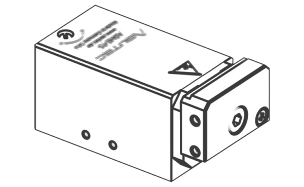
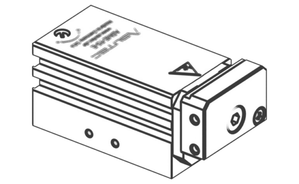
ASME-95
For workpiece carrier loads from 3 kg up to 95 kg
Two air connection ports (extending and retracting the stop)
With flat stop plate
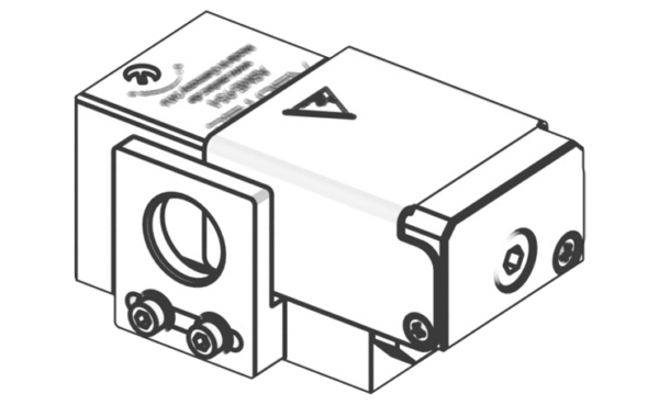
ASME-95-E
For workpiece carrier loads from 3 kg up to 95 kg
Two air connection ports (extending and retracting the stop)
Option to query the stop positions using T-slot magnetic field sensors.
With flat stop plate
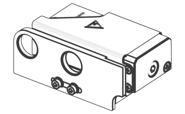
ASME-95-I
For workpiece carrier loads from 3 kg up to 95 kg
Two air connection ports (extending and retracting the stop)
Option to query the retracted stop position using an M12x1 inductive sensor.
With flat stop plate
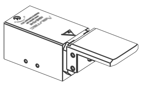
ASME-95-I-001
For workpiece carrier loads from 3 kg up to 95 kg
Two air connection ports (extending and retracting the stop)
Both stop positions (retracted and extended) can be monitored using inductive sensors M12x1.
With flat stop plate
ASME-95-W
For workpiece carrier loads from 3 kg up to 95 kg
Two air connection ports (extending and retracting the stop)
With short L-shape stop
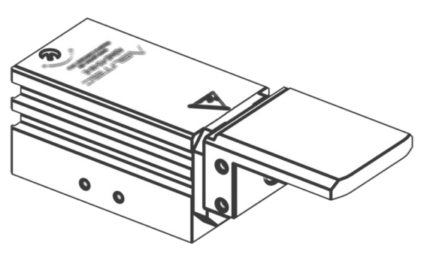
ASME-95-W-E
For workpiece carrier loads from 3 kg up to 95 kg
Two air connection ports (extending and retracting the stop)
Option to query the stop positions using T-slot magnetic field sensors.
With short L-shape stop
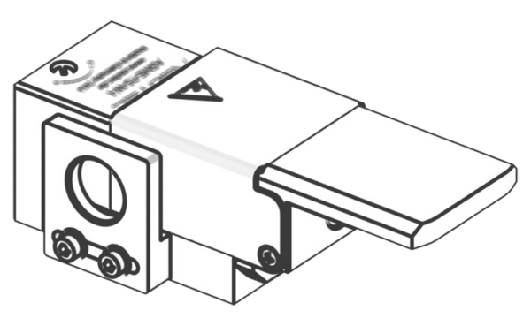
ASME-95-W-I
For workpiece carrier loads from 3 kg up to 95 kg
Two air connection ports (extending and retracting the stop)
Option to query the retracted stop position using an M12x1 inductive sensor.
With short L-shape stop
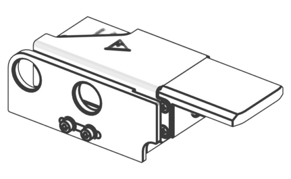
ASME-95-W-I-002
For workpiece carrier loads from 3 kg up to 95 kg
Two air connection ports (extending and retracting the stop)
Both stop positions (retracted and extended) can be monitored using inductive sensors M12x1.
With short L-shape stop
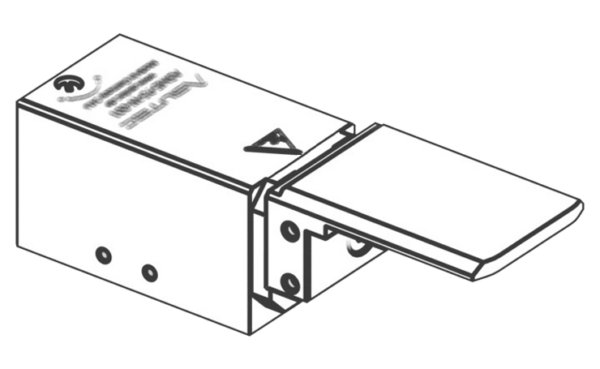
ASME-95-W-001
For workpiece carrier loads from 3 kg up to 95 kg
Two air connection ports (extending and retracting the stop)
With long L-shape stop
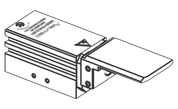
ASME-95-W-E-001
For workpiece carrier loads from 3 kg up to 95 kg
Two air connection ports (extending and retracting the stop)
Option to query the stop positions using T-slot magnetic field sensors.
With long L-shape stop
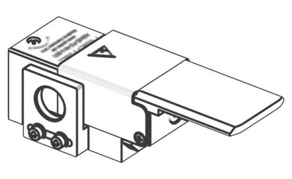
ASME-95-W-I-001
For workpiece carrier loads from 3 kg up to 95 kg
Two air connection ports (extending and retracting the stop)
Option to query the retracted stop position using an M12x1 inductive sensor.
With long L-shape stop
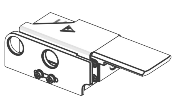
ASME-95-W-I-003
For workpiece carrier loads from 3 kg up to 95 kg
Two air connection ports (extending and retracting the stop)
Both stop positions (retracted and extended) can be monitored using inductive sensors M12x1.
With long L-shape stop
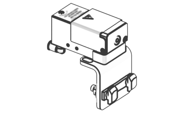
ASME-95-100
For workpiece carrier loads from 3 kg up to 95 kg
Two air connection ports (extending and retracting the stop)
With flat stop plate, mounting bracket (suitable for side mounting to a section profile)
Delivery includes stop cover, mounting bracket, and air connections 14010004.
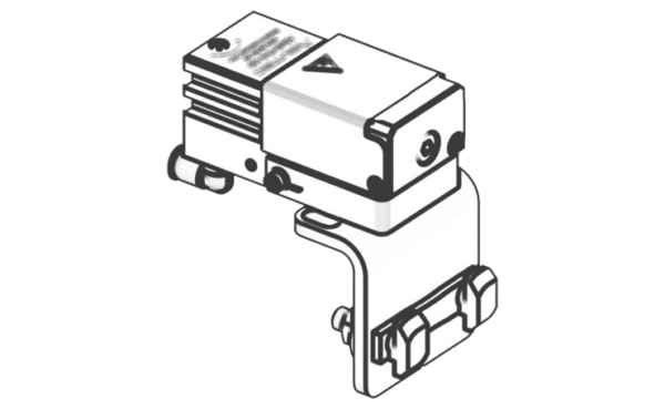
ASME-95-E-100
For workpiece carrier loads from 3 kg up to 95 kg
Two air connection ports (extending and retracting the stop)
Option to query the stop positions using T-slot magnetic field sensors.
With flat stop plate, mounting bracket (suitable for side mounting to a section profile)
Delivery includes stop cover, mounting bracket, and air connections 14010004.
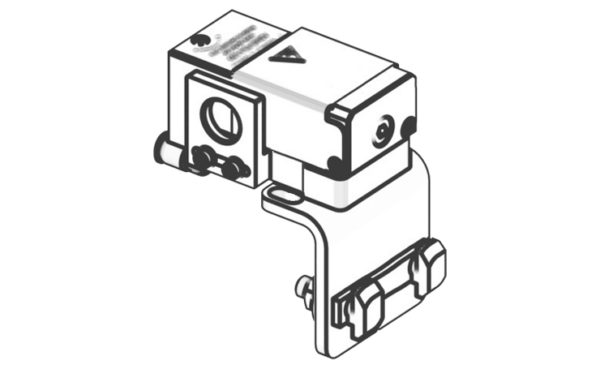
ASME-95-I-100
For workpiece carrier loads from 3 kg up to 95 kg
Two air connection ports (extending and retracting the stop)
Option to query the retracted stop position using an M12x1 inductive sensor.
With flat stop plate, mounting bracket (suitable for side mounting to a section profile)
Delivery includes stop cover, mounting bracket, and air connections 14010004.
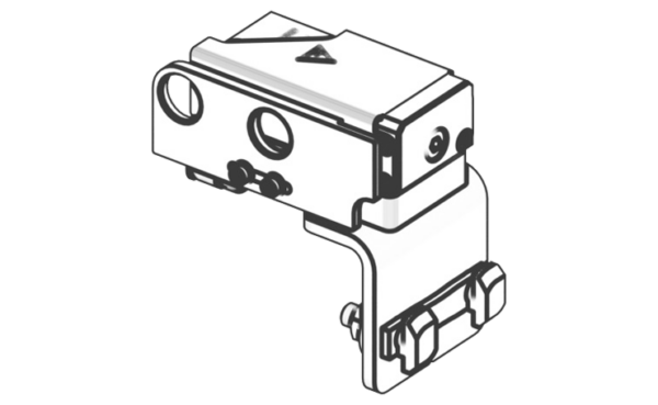
ASME-95-I-101
For workpiece carrier loads from 3 kg up to 95 kg
Two air connection ports (extending and retracting the stop)
Both stop positions (retracted and extended) can be monitored using inductive sensors M12x1.
With flat stop plate, mounting bracket (suitable for side mounting to a section profile)
Delivery includes stop cover, mounting bracket, and air connections 14010004.
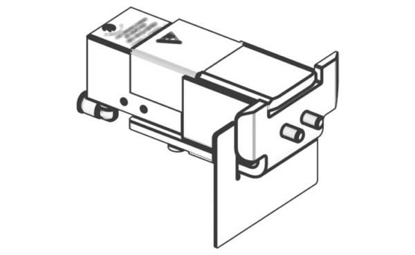
ASME-95-W-100
For workpiece carrier loads from 3 kg up to 95 kg
Two air connection ports (extending and retracting the stop)
With short L-shape stop, mounting bracket (suitable for mounting on Bosch Rexroth HQ 2/U)
Delivery includes stop cover, mounting bracket, and air connections 14010004.
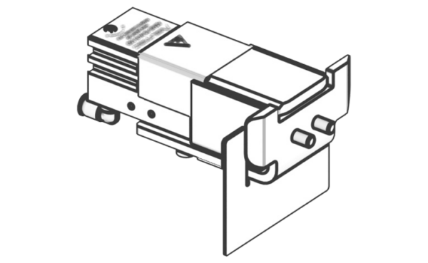
ASME-95-W-E-100
For workpiece carrier loads from 3 kg up to 95 kg
Two air connection ports (extending and retracting the stop)
Option to query the stop positions using T-slot magnetic field sensors.
With short L-shape stop, mounting bracket (suitable for mounting on Bosch Rexroth HQ 2/U)
Delivery includes stop cover, mounting bracket, and air connections 14010004.
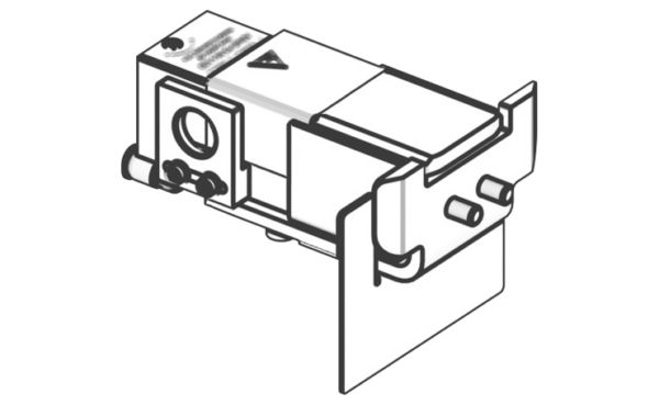
ASME-95-W-I-100
For workpiece carrier loads from 3 kg up to 95 kg
Two air connection ports (extending and retracting the stop)
Option to query the retracted stop position using an M12x1 inductive sensor.
With short L-shape stop, mounting bracket (suitable for mounting on Bosch Rexroth HQ 2/U)
Delivery includes stop cover, mounting bracket, and air connections 14010004.
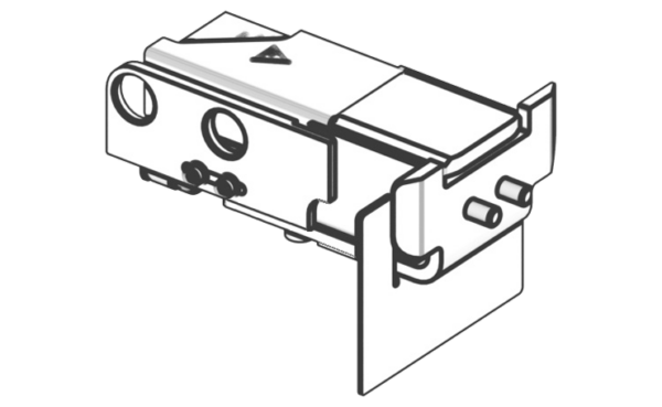
ASME-95-W-I-101
For workpiece carrier loads from 3 kg up to 95 kg
Two air connection ports (extending and retracting the stop)
Both stop positions (retracted and extended) can be monitored using inductive sensors M12x1.
With short L-shape stop, mounting bracket (suitable for mounting on Bosch Rexroth HQ 2/U)
Delivery includes stop cover, mounting bracket, and air connections 14010004.
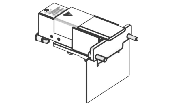
ASME-95-W-101
For workpiece carrier loads from 3 kg up to 95 kg
Two air connection ports (extending and retracting the stop)
With long L-shape stop, mounting bracket (suitable for mounting on Bosch Rexroth HQ 2/U2)
Delivery includes stop cover, mounting bracket, and air connections 14010004.
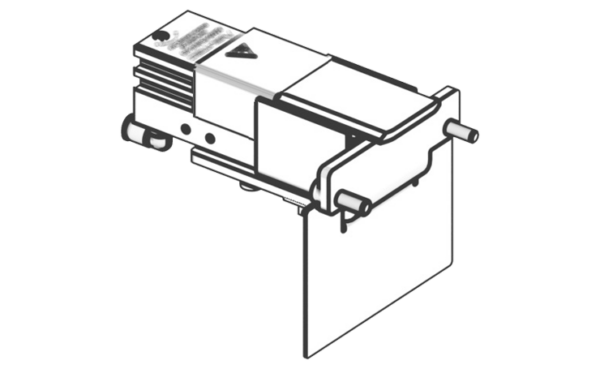
ASME-95-W-E-101
For workpiece carrier loads from 3 kg up to 95 kg
Two air connection ports (extending and retracting the stop)
Option to query the stop positions using T-slot magnetic field sensors.
With long L-shape stop, mounting bracket (suitable for mounting on Bosch Rexroth HQ 2/U2)
Delivery includes stop cover, mounting bracket, and air connections 14010004.
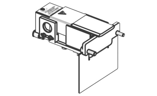
ASME-95-W-I-102
For workpiece carrier loads from 3 kg up to 95 kg
Two air connection ports (extending and retracting the stop)
Option to query the retracted stop position using an M12x1 inductive sensor.
With long L-shape stop, mounting bracket (suitable for mounting on Bosch Rexroth HQ 2/U2)
Delivery includes stop cover, mounting bracket, and air connections 14010004.
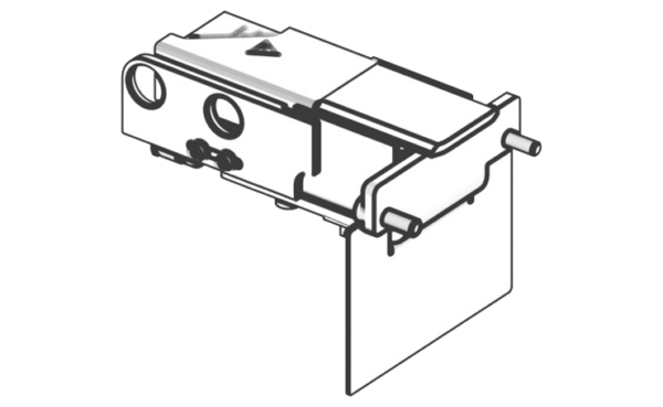
ASME-95-W-I-103
For workpiece carrier loads from 3 kg up to 95 kg
Two air connection ports (extending and retracting the stop)
Both stop positions (retracted and extended) can be monitored using inductive sensors M12x1.
With long L-shape stop, mounting bracket (suitable for mounting on Bosch Rexroth HQ 2/U2)
Delivery includes stop cover, mounting bracket, and air connections 14010004.
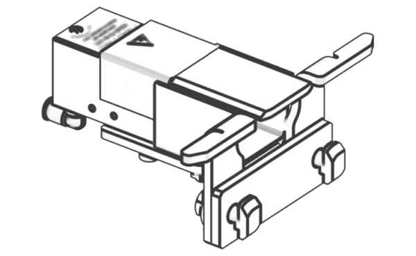
ASME-95-W-102
With 30 mm damping stroke
For workpiece carrier loads from 3 kg up to 95 kg
Two air connection ports (extending and retracting the stop)
With long L-shape stop, mounting bracket, and intermediate plate (suitable for mounting on Bosch Rexroth HQ 2/U-H and HQ 2/C-H)
Delivery includes stop cover, mounting bracket, and air connections 14010004.
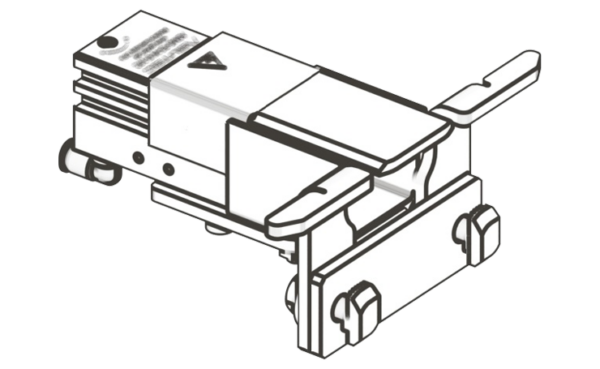
ASME-95-W-E-102
For workpiece carrier loads from 3 kg up to 95 kg
Two air connection ports (extending and retracting the stop)
Option to query the stop positions using T-slot magnetic field sensors.
With long L-shape stop, mounting bracket, and intermediate plate (suitable for mounting on Bosch Rexroth HQ 2/U-H and HQ 2/C-H)
Delivery includes stop cover, mounting bracket, and air connections 14010004.
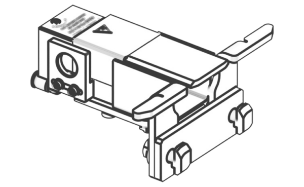
ASME-95-W-I-104
For workpiece carrier loads from 3 kg up to 95 kg
Two air connection ports (extending and retracting the stop)
Option to query the retracted stop position using an M12x1 inductive sensor.
With long L-shape stop, mounting bracket, and intermediate plate (suitable for mounting on Bosch Rexroth HQ 2/U-H and HQ 2/C-H)
Delivery includes stop cover, mounting bracket, and air connections 14010004.
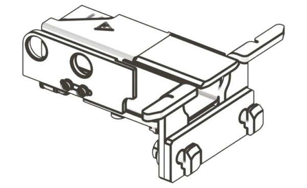
ASME-95-W-I-105
For workpiece carrier loads from 3 kg up to 95 kg
Two air connection ports (extending and retracting the stop)
Both stop positions (retracted and extended) can be monitored using inductive sensors M12x1.
With long L-shape stop, mounting bracket, and intermediate plate (suitable for mounting on Bosch Rexroth HQ 2/U-H and HQ 2/C-H)
Delivery includes stop cover, mounting bracket, and air connections 14010004.